Assignment
read pages 143-152
Project 3 due next week 2/14/09
Project 3
Create a landscape that incorporates the following:
1. Buildings in two-point perspective
2. Shading and cast shadows
3. Reflections on glass, water, or metal
4. Foliage
5. Figures
6. Lettering (i.e. signs)
The drawing should be no smaller than 18 x 24 inches on bond paper using
both pencil and ballpoint pen.

Sunday, February 8, 2009


Friday, February 6, 2009
Trung class: GE253, wk#8
Trung class: GE253, wk#8: temperature and Kinetics (gas and perfect gas)
Please read chapter 8 and do two problems
Please make sure you understand the US and SI unit systems
Make sure you understand the calculation of temperature conversions (F to C to K)
And pV=nRt as well as the K(b) constant.
Please visit: http://wps.pearsoncustom.com/pcp_wilson_ittphysics_5/32/8224/2105451.cw/-/t/index.html (or just simply click on this link) to explore each online chapter. Then do one practice test (chapter 8).
Please use this online website automatic sender option to send the automatic computer graded result to the course instructor: trungtchiong@yahoo.com or ttchiong@itt-tech.edu.
We will be using this online physics website for our chapter 9,10 homeworks as well.
You will be sending the computer graded homework to the same above email address(es). And you are allowed to have infinite time and trials in this website.
Please read chapter 8 and do two problems
Please make sure you understand the US and SI unit systems
Make sure you understand the calculation of temperature conversions (F to C to K)
And pV=nRt as well as the K(b) constant.
Please visit: http://wps.pearsoncustom.com/pcp_wilson_ittphysics_5/32/8224/2105451.cw/-/t/index.html (or just simply click on this link) to explore each online chapter. Then do one practice test (chapter 8).
Please use this online website automatic sender option to send the automatic computer graded result to the course instructor: trungtchiong@yahoo.com or ttchiong@itt-tech.edu.
We will be using this online physics website for our chapter 9,10 homeworks as well.
You will be sending the computer graded homework to the same above email address(es). And you are allowed to have infinite time and trials in this website.
Trung class: CD-240. Week #8 (2/6/09)
Trung class: CD-240. Week #8 (2/6/09)
Please read chapter 8 (p420-440) that covers the following:
1: Scalar and vector (make sure you understand the differences between them)
2: Three Newton's Laws and their applications
3: Right triangle calculation with a^2 + b^2 = c^2
4: Non-right triangle (no angle is 90 degrees): use law of sines and cosines
5: Unit conversions
6: Gravity, acceleration and forces
Please be aware that these materials will be used in your future Physics course.
Next week I will review a portion of the final exam with all students.
Please read chapter 8 (p420-440) that covers the following:
1: Scalar and vector (make sure you understand the differences between them)
2: Three Newton's Laws and their applications
3: Right triangle calculation with a^2 + b^2 = c^2
4: Non-right triangle (no angle is 90 degrees): use law of sines and cosines
5: Unit conversions
6: Gravity, acceleration and forces
Please be aware that these materials will be used in your future Physics course.
Next week I will review a portion of the final exam with all students.
Wednesday, February 4, 2009
Trung class - Math 2, week 8, Permutation/Combination
Please use www.interactmath.com to review permutation and combination.
Then challenge your knowledge by solving problem 77 on page 249
Next week is probability
Then challenge your knowledge by solving problem 77 on page 249
Next week is probability
Sunday, February 1, 2009
Thursday, January 29, 2009
Physics, GE253, wk#7
Trung class: GE253, wk#7
Please read chapter 7 and do two problems
Please make sure you understand stress, strain, Young's modulus in solid section
Please make sure you understand the differences between solid and fluid
Please make sure you understand the calculation of pressure in fluid as well as the major impact of the "h" variable in calculating pressure.
It is best to revisit the calculation of area and volume of a cylinder
Please visit: http://wps.pearsoncustom.com/pcp_wilson_ittphysics_5/32/8224/2105451.cw/-/t/index.html (or just simply click on this link) to explore each online chapter. Then use ch.1 to 6 to do the make-up tests. Then use this online website automatic sender option to send the automatic computer graded result to the course instructor: trungtchiong@yahoo.com or ttchiong@itt-tech.edu.
We will be using this online physics website for our chapter 8,9,10 homeworks. You will be sending the computer graded homework to the same above email address(es). And you are allowed to have infinite time and trials in this website.
Have fun!
Thanks.
Please read chapter 7 and do two problems
Please make sure you understand stress, strain, Young's modulus in solid section
Please make sure you understand the differences between solid and fluid
Please make sure you understand the calculation of pressure in fluid as well as the major impact of the "h" variable in calculating pressure.
It is best to revisit the calculation of area and volume of a cylinder
Please visit: http://wps.pearsoncustom.com/pcp_wilson_ittphysics_5/32/8224/2105451.cw/-/t/index.html (or just simply click on this link) to explore each online chapter. Then use ch.1 to 6 to do the make-up tests. Then use this online website automatic sender option to send the automatic computer graded result to the course instructor: trungtchiong@yahoo.com or ttchiong@itt-tech.edu.
We will be using this online physics website for our chapter 8,9,10 homeworks. You will be sending the computer graded homework to the same above email address(es). And you are allowed to have infinite time and trials in this website.
Have fun!
Thanks.
Wednesday, January 28, 2009
Physics- GE 253
Trung class: Before you come to class on Thursday night (1/29/2009) please visit the provided website:
http://www.pearsoncustom.com/itt/GE253_Physics/
and try out some problems on work and energy as well as momentum and collision problems.
Please use this website to send the result to my school email: ttchiong@itt-tech.edu
How?
Click on the link, click on the companion website, click on instructor icon (at the bottom of the screen), then click on TOC (ex: http://wps.pearsoncustom.com/pcp_wilson_ittphysics_5/32/8224/2105451.cw/-/t/index.html) The select related chapters.
This is a trial run, please do not hesitate to send the results.
Have fun!
http://www.pearsoncustom.com/itt/GE253_Physics/
and try out some problems on work and energy as well as momentum and collision problems.
Please use this website to send the result to my school email: ttchiong@itt-tech.edu
How?
Click on the link, click on the companion website, click on instructor icon (at the bottom of the screen), then click on TOC (ex: http://wps.pearsoncustom.com/pcp_wilson_ittphysics_5/32/8224/2105451.cw/-/t/index.html) The select related chapters.
This is a trial run, please do not hesitate to send the results.
Have fun!
Math II , wk#7 - Ch.4
Please read chapter 4 and use www.interactmath.com to solve 4 problems on geometric and arithmetic series. Then do one problem on summation of the first 4 terms of a given geometric series.
Have a great day!
Have a great day!
Sunday, January 25, 2009
CD140
This week assignment is to read pages 99-122
Project 2 is Due Saturday 1/31/09.
Project 2
Students should create a black-and-white drawing of a still life they can assemble
at home. They should explore the full range of values that they have on their tenstep
value chart. The drawing should be presented to the class during the sixth unit.
Project 2 is Due Saturday 1/31/09.
Project 2
Students should create a black-and-white drawing of a still life they can assemble
at home. They should explore the full range of values that they have on their tenstep
value chart. The drawing should be presented to the class during the sixth unit.
Friday, January 23, 2009
Trung CD-240, week#6
Please read vector geometry and scalar geometry
Then do 2hws on vector geometry and 2 for the scalar geometry
Please work on the Inventor step-by-step package to create the solid model of the bracket and its drawing with views (third angle projection). Please use AutoDesk INVENTOR software. Do not use AutoCAD to produce this assignment.
Thanks.
Then do 2hws on vector geometry and 2 for the scalar geometry
Please work on the Inventor step-by-step package to create the solid model of the bracket and its drawing with views (third angle projection). Please use AutoDesk INVENTOR software. Do not use AutoCAD to produce this assignment.
Thanks.
Physics - GE253 week 6
Trung- Physics, wk#6:
Please read the work and power chapter. Then do 4 problems on work (kinetic and potential energy and displacement) and power (work over a period).
Please submit your team project on week #7.
Thanks.
Please read the work and power chapter. Then do 4 problems on work (kinetic and potential energy and displacement) and power (work over a period).
Please submit your team project on week #7.
Thanks.
Math 2, week 6
Trung - GE 192: Math 2.
Please read the Vector chapter and do 4 problems on adding and dot product.
Thanks.
Please read the Vector chapter and do 4 problems on adding and dot product.
Thanks.
Sunday, January 18, 2009
Friday, January 16, 2009
CD 240: Descriptive Geometry
Instructor: Trung Tchiong
Please read the tolerance chapter and do two problems on this area.
1: Calculate the clearance of a shaft and bearing assembly (use www.sdp-si.com for part dimensions)
2: Calculate the Interference of the shaft and bearing assembly (use the same website). Please use the shaft size of dia. .375in +/- .001in and maximum interference of .004in
3: Please work on your final package (due wk#11) and the Inventor package (due 1/30).
Have a great weekend!
Instructor: Trung Tchiong
Please read the tolerance chapter and do two problems on this area.
1: Calculate the clearance of a shaft and bearing assembly (use www.sdp-si.com for part dimensions)
2: Calculate the Interference of the shaft and bearing assembly (use the same website). Please use the shaft size of dia. .375in +/- .001in and maximum interference of .004in
3: Please work on your final package (due wk#11) and the Inventor package (due 1/30).
Have a great weekend!
Thursday, January 15, 2009
Trung/ Physics course: week 5- work and energy ch.5
Please read ch.5 and do two problems on work and potential energy.
Please contact Dean Varma prior to bringing in supplies to complete your team projects. Please do not bring any supplies that did not have the final approval from our Dean.
Make sure you communicate with your team members so that the prototype and the report is done at 9PM on week #6.
Test#2 is scheduled on week #7.
Have a funfilled day!
Please contact Dean Varma prior to bringing in supplies to complete your team projects. Please do not bring any supplies that did not have the final approval from our Dean.
Make sure you communicate with your team members so that the prototype and the report is done at 9PM on week #6.
Test#2 is scheduled on week #7.
Have a funfilled day!
Civil Drafting - Class #5
CD 310 - Civil Drafting and Introduction to GIS
January 15, 2009 - Class #5
Richard Pardys, Instructor, Phone - 215-763-0842, rpardys@itt-tech.edu
Lab tonight
Coordinate with your classmates, and demarcate the area of the island that you will be working on.
I will talk with each of you individually about your particular project, and the sheets you should be developing. Work in class today will help you get a start on what’s due for your 30% next week.
Homework
Read Chapter 5For Chapter 5, do the odd text questions on pp 111-112, and problems P5-1 and P5-2 a and b on pp 112 and 113
January 15, 2009 - Class #5
Richard Pardys, Instructor, Phone - 215-763-0842, rpardys@itt-tech.edu
Lab tonight
Coordinate with your classmates, and demarcate the area of the island that you will be working on.
I will talk with each of you individually about your particular project, and the sheets you should be developing. Work in class today will help you get a start on what’s due for your 30% next week.
Homework
Read Chapter 5For Chapter 5, do the odd text questions on pp 111-112, and problems P5-1 and P5-2 a and b on pp 112 and 113
Wednesday, January 14, 2009
Math ii: trung class, GE192.
Week#5
Please review law of sines and cosines
Please read ch. 3.4 for complex number
Please use www.interactmath.com to review ch. 3.4 (do 4 exercises)
Submit 4 solved problems to Trung by next class.
Thanks.
Week#5
Please review law of sines and cosines
Please read ch. 3.4 for complex number
Please use www.interactmath.com to review ch. 3.4 (do 4 exercises)
Submit 4 solved problems to Trung by next class.
Thanks.
My Regards from Syria


hello all
I would like to say Happy new year to every one..
sorry being late.. I will see you all on Monday 1/19/2009
looking to see you
Ashraf
Intro to Drafting and Design - Class #5
CD 111 Introduction to Design and Drafting
January 15, 2009 Class #5
Richard Pardys, Instructor, Phone - 215-763-0842, rpardys@itt-tech.edu
Homework due Next Week
Read Chapter 5.
Answer the 5 review questions and give a definition for all the keywords on page 155.
Study for your Midterm
Midterm next week
25 multiple choice questions
Worth 15% of your total grade.
January 15, 2009 Class #5
Richard Pardys, Instructor, Phone - 215-763-0842, rpardys@itt-tech.edu
Homework due Next Week
Read Chapter 5.
Answer the 5 review questions and give a definition for all the keywords on page 155.
Study for your Midterm
Midterm next week
25 multiple choice questions
Worth 15% of your total grade.
Monday, January 12, 2009
Capstone - Class #5
CD 331 Design and Drafting Capstone Project
January 12, 2009 Week #5
Richard Pardys, Instructor, Phone - 215-763-0842, rpardys@itt-tech.edu
Homework due next Week
Reading
Read Chapter 4.
Group Manual Homework
Develop a Project Description, Design Specifications and Design Description. The requirements for these are shown on page 83, Section 3.3 of your book. Each of these three items should be long enough to develop the issue completely. The Design Description requires preparing drawings to go with your work. The drawings should be reduced if necessary to fit on an 8 ½ x 11 report format. This is to be handed in next week. This is a group effort, and you all will be graded on it.
Prepare a contract letter to go in the manual. All your group members must sign the contract letter along with me. I am the client in each case. See Appendix D on page 259 in your book for a sample of how to make this letter.
Also, please hand in the “List of Drawings”, “List of Tasks” and the “Bar-Chart Schedule” and the budget..
30% Pin-Up Next Week
Refine all your drawings in sketch form. Add at least one new sheet per student.
All sketches should be a minimum size of 18” x 24”.
We’ll begin putting this on CAD next week after the 30% Review.
January 12, 2009 Week #5
Richard Pardys, Instructor, Phone - 215-763-0842, rpardys@itt-tech.edu
Homework due next Week
Reading
Read Chapter 4.
Group Manual Homework
Develop a Project Description, Design Specifications and Design Description. The requirements for these are shown on page 83, Section 3.3 of your book. Each of these three items should be long enough to develop the issue completely. The Design Description requires preparing drawings to go with your work. The drawings should be reduced if necessary to fit on an 8 ½ x 11 report format. This is to be handed in next week. This is a group effort, and you all will be graded on it.
Prepare a contract letter to go in the manual. All your group members must sign the contract letter along with me. I am the client in each case. See Appendix D on page 259 in your book for a sample of how to make this letter.
Also, please hand in the “List of Drawings”, “List of Tasks” and the “Bar-Chart Schedule” and the budget..
30% Pin-Up Next Week
Refine all your drawings in sketch form. Add at least one new sheet per student.
All sketches should be a minimum size of 18” x 24”.
We’ll begin putting this on CAD next week after the 30% Review.
Intro to AutoCAD Class #5
CD 121 Drafting and CAD Methods
January 13, 2009 – Class #5
Richard Pardys, Instructor, Phone - 215-763-0842, rpardys@itt-tech.edu
Lab Today
Tonight until 10:00, Draw either the calculator or the front view of the ’32 Ford Special. Both are on page 218, but the instructions for the calculator are on page 217. You do not need to draw the side view of the car, as this was last week’s assignment. You will get extra credit if you’re able to do both activities by 10:00.
Homework for next week
Read Chapter 6 in your book.
Do the Multiple Choice exercises 1 to 8, and the True/False Questions 1-7 at the end of the chapter.
Practice for your midterm.
Midterm Exam
Next Week. Worth 15% of your grade
January 13, 2009 – Class #5
Richard Pardys, Instructor, Phone - 215-763-0842, rpardys@itt-tech.edu
Lab Today
Tonight until 10:00, Draw either the calculator or the front view of the ’32 Ford Special. Both are on page 218, but the instructions for the calculator are on page 217. You do not need to draw the side view of the car, as this was last week’s assignment. You will get extra credit if you’re able to do both activities by 10:00.
Homework for next week
Read Chapter 6 in your book.
Do the Multiple Choice exercises 1 to 8, and the True/False Questions 1-7 at the end of the chapter.
Practice for your midterm.
Midterm Exam
Next Week. Worth 15% of your grade
Friday, January 9, 2009
Math 2 - Wk#4
Please visit www.interactmath.com to practice all missing homework. There you will find a step by step and look-alike problems for practicing
Please review all 6 properties of Log
Please review and work on 4 problems of Law of Sines and Cosines
Quiz: Goto page 135, example 1. Give yourselve dimensions of 3 edges of this triangle as printed in the book: c=56in; a=45.2in and b=59.4in
Find: all three missing angles. Make sure you show step-by-step solution. Then compare your number to the book.
Have a great day!
Please review all 6 properties of Log
Please review and work on 4 problems of Law of Sines and Cosines
Quiz: Goto page 135, example 1. Give yourselve dimensions of 3 edges of this triangle as printed in the book: c=56in; a=45.2in and b=59.4in
Find: all three missing angles. Make sure you show step-by-step solution. Then compare your number to the book.
Have a great day!
Physics class- Wk#4 Newton 3 laws
Read chapter 3 with 3 Newton's Laws
Do submit problem #25 (ch.3)
Work on your team/individual project
Notes: One of your classmates had done the Fire-lantern (Ch.8; temperature)- Good Job!
Have a great day!
Do submit problem #25 (ch.3)
Work on your team/individual project
Notes: One of your classmates had done the Fire-lantern (Ch.8; temperature)- Good Job!
Have a great day!
CD-240 Descriptive Geometry - Friday night, wk4
Read chapter 4
Sketch the revolve section of our ITT-KOP trash can
Use AutoCAD to re-produce the same drawing with dimensions
Work on the Final design package.
See the Instructor for additional questions.
Have a great day!
Sketch the revolve section of our ITT-KOP trash can
Use AutoCAD to re-produce the same drawing with dimensions
Work on the Final design package.
See the Instructor for additional questions.
Have a great day!
Wednesday, January 7, 2009
Intro to Drafting and Design - Class #4
CD 111 Introduction to Design and Drafting
January 8, 2009 Class #4
Richard Pardys, Instructor, Phone - 215-763-0842, rpardys@itt-tech.edu
Homework due Next Week
Read Chapter 4, and answer questions 1-9 on page 120.
On page 124, sketch front, top and right-side views for items 1,2,3 and 5. Do each of these four items on one 8.5 x 11 sheet. Each sheet should have three views of the particular item, and each view should be labeled. Sketches should be proportionate in size as to what is in the book. Measuring is nit needed.
Midterm is two weeks
25 multiple choice questions
Worth 15% of your total grade.
We’ll review for it next week.
January 8, 2009 Class #4
Richard Pardys, Instructor, Phone - 215-763-0842, rpardys@itt-tech.edu
Homework due Next Week
Read Chapter 4, and answer questions 1-9 on page 120.
On page 124, sketch front, top and right-side views for items 1,2,3 and 5. Do each of these four items on one 8.5 x 11 sheet. Each sheet should have three views of the particular item, and each view should be labeled. Sketches should be proportionate in size as to what is in the book. Measuring is nit needed.
Midterm is two weeks
25 multiple choice questions
Worth 15% of your total grade.
We’ll review for it next week.
Monday, January 5, 2009
Intro to AutoCAD Class #4
CD 121 Drafting and CAD Methods
January 6, 2009 – Class #4
Richard Pardys, Instructor, Phone - 215-763-0842, rpardys@itt-tech.edu
Lab Today
Tonight until 10:00, do either 4-1 or 4-2 on page 166. You may do the second problem for extra credit. Total extra-credit value – 110%.
Homework for next week
Read Chapter 5 in your book from page 173 to 194 and 202 to 216. Information on advanced snapping modes is not necessary.
Do all multiple choice questions at the end of the chapter except numbers 9, 10, and 11.and all true/false questions at the end of the chapter except numbers 8 and 9.
January 6, 2009 – Class #4
Richard Pardys, Instructor, Phone - 215-763-0842, rpardys@itt-tech.edu
Lab Today
Tonight until 10:00, do either 4-1 or 4-2 on page 166. You may do the second problem for extra credit. Total extra-credit value – 110%.
Homework for next week
Read Chapter 5 in your book from page 173 to 194 and 202 to 216. Information on advanced snapping modes is not necessary.
Do all multiple choice questions at the end of the chapter except numbers 9, 10, and 11.and all true/false questions at the end of the chapter except numbers 8 and 9.
Capstone Class #4 Homework
CD 331 Design and Drafting Capstone Project
January 5, 2009 Week #4
Richard Pardys, Instructor, Phone - 215-763-0842, rpardys@itt-tech.edu
Homework due next Week
Reading
Read Chapter 4.
Group Manual Homework
Develop a Project Description, Design Specifications and Design Description. The requirements for these are shown on page 83, Section 3.3 of your book. Each of these three items should be long enough to develop the issue completely. The Design Description requires preparing drawings to go with your work. The drawings should be reduced if necessary to fit on an 8 ½ x 11 report format. This is to be handed in next week. This is a group effort, and you all will be graded on it.
Prepare a contract letter to go in the manual. All your group members must sign the contract letter along with me. I am the client in each case. See Appendix D on page 259 in your book for a sample of how to make this letter.
Also, please hand in the “List of Drawings”, “List of Tasks” and the “Bar-Chart Schedule” and the budget..
30% Pin-Up Next Week
Refine all your drawings in sketch form. Add at least one new sheet per student.
All sketches should be a minimum size of 18” x 24”.
We’ll begin putting this on CAD next week after the 30% Review.
January 5, 2009 Week #4
Richard Pardys, Instructor, Phone - 215-763-0842, rpardys@itt-tech.edu
Homework due next Week
Reading
Read Chapter 4.
Group Manual Homework
Develop a Project Description, Design Specifications and Design Description. The requirements for these are shown on page 83, Section 3.3 of your book. Each of these three items should be long enough to develop the issue completely. The Design Description requires preparing drawings to go with your work. The drawings should be reduced if necessary to fit on an 8 ½ x 11 report format. This is to be handed in next week. This is a group effort, and you all will be graded on it.
Prepare a contract letter to go in the manual. All your group members must sign the contract letter along with me. I am the client in each case. See Appendix D on page 259 in your book for a sample of how to make this letter.
Also, please hand in the “List of Drawings”, “List of Tasks” and the “Bar-Chart Schedule” and the budget..
30% Pin-Up Next Week
Refine all your drawings in sketch form. Add at least one new sheet per student.
All sketches should be a minimum size of 18” x 24”.
We’ll begin putting this on CAD next week after the 30% Review.
Sunday, January 4, 2009
CD140 Rapid Visualization
Welcome back students from the holidays! This Saturday 1/10/09 we will pick up with Unit 3. Please read pages 54-71 of your text books for your assignmnet prior to class.
~See you Saturday,
Mr. Grenon
~See you Saturday,
Mr. Grenon
Friday, December 19, 2008
CD240 Descriptive Geometry, week#3- Auxiliary View
After completing this unit, the student will have the opportunity to:
1. Define auxiliary view, primary auxiliary view, secondary auxiliary view, and successive
auxiliary view.
2. Describe the function of auxiliary views.
3. Identify and describe the difference between the two methods used for the construction of
auxiliary views.
4. Construct primary, secondary, and successive auxiliary views using the folding-line
method.
Homework: Submit two set of drawings of a simple part (ref. www.sdp-si.com, select a simple bearing). The first set uses 3rd angle projection. The second set uses 1st angle projection.
Lab: (#6 and #7 exercise)
Produce one auxilary view for exercise #6
Produce one auxilary view for exercise #7
Produce hand-sketches of one auxilary view for exercise #6
Produce hand-sketches of one auxilary view for exercise #7
Inventory: When you return from the break, please submit all drawings to the course instructor.
Thank you very much and have a great holidays and happy new year!
1. Define auxiliary view, primary auxiliary view, secondary auxiliary view, and successive
auxiliary view.
2. Describe the function of auxiliary views.
3. Identify and describe the difference between the two methods used for the construction of
auxiliary views.
4. Construct primary, secondary, and successive auxiliary views using the folding-line
method.
Homework: Submit two set of drawings of a simple part (ref. www.sdp-si.com, select a simple bearing). The first set uses 3rd angle projection. The second set uses 1st angle projection.
Lab: (#6 and #7 exercise)
Produce one auxilary view for exercise #6
Produce one auxilary view for exercise #7
Produce hand-sketches of one auxilary view for exercise #6
Produce hand-sketches of one auxilary view for exercise #7
Inventory: When you return from the break, please submit all drawings to the course instructor.
Thank you very much and have a great holidays and happy new year!
Thursday, December 18, 2008
Math II - Week#3
Students are able to perform the following:
Chapter 2, Section 2.1, “Exponential Functions,”
pp. 66–78
o Chapter 2, Section 2.2, “Logarithmic Functions,”
pp. 78–90
o Chapter 2, Section 2.3, “Properties of Logarithms of A*B, A/B, A^x, change base"
pp. 90–99
Chapter 2, Section 2.1, “Exponential Functions,”
pp. 66–78
o Chapter 2, Section 2.2, “Logarithmic Functions,”
pp. 78–90
o Chapter 2, Section 2.3, “Properties of Logarithms of A*B, A/B, A^x, change base"
pp. 90–99
Physics Chapter 3, week #3
The student will be able to (chapter 3)
1. analyze motion in terms of its components and apply the kinematic equations to
components of motion.
2. learn vector notation, add and subtract vectors graphically and analytically, and use
vectors to describe motion in two dimensions.
3. determine relative velocities through vector addition and subtraction.
4. analyze projectile motion to find position, time of flight, and range.
students should try to solve the following:
Exercises 18, 30, 38, 46, 56, 66, 78, 88, and 94 in
Chapter 3 on pages 95 to 100 of the text.
And review the law of sine and cosine
1. analyze motion in terms of its components and apply the kinematic equations to
components of motion.
2. learn vector notation, add and subtract vectors graphically and analytically, and use
vectors to describe motion in two dimensions.
3. determine relative velocities through vector addition and subtraction.
4. analyze projectile motion to find position, time of flight, and range.
students should try to solve the following:
Exercises 18, 30, 38, 46, 56, 66, 78, 88, and 94 in
Chapter 3 on pages 95 to 100 of the text.
And review the law of sine and cosine
Wednesday, December 17, 2008
Graduation of Dec 08 on Thursday 12/18/2008

We will hold our December graduation Thursday, December 18, 7PM at the Radisson Hotel and Convention Center in KOP. It is an excellent venue all will enjoy and remember. If your schedule allows, please attend. The atmosphere is electric. It is the fulfillment of a dream for our graduating students. This is why we do what we do. Come and share in the excitement.
Computer Drafting and Design Graduates:
Giovanni Iannuzi
Brian Breitinger
Striling Rolland
Multimedia Graduates:
Andrew Andrwick
Anthony Alston
Michael Shaw
Aaron Chaney
Akim Crump
Sheena Viruet
Michael Cirio
Linus Kang
Congratulation to all of the students who have achieved their goals.
chair of CDD and MM in ITT
Tuesday, December 16, 2008
CD210-Engineering Graphics I / Charlie Scandone Monday Night
LAB ASSIGNMENT WEEK 1
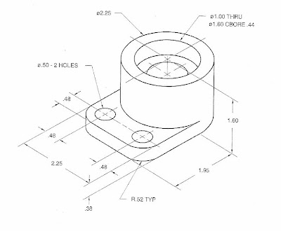
1) Re-create the drawing above in AutoCAD. Make sure that all the dimensions are
correct and that the part is drawn to the same exact image as above.
2) First, open the following toolbars and place them on your screen, VIEW, SOLIDS MODELING, DIMENSIONS, MODIFY, and DRAWING.
3) Next, open a template. To do this, go to the insert tab and click, layout/layout from template/sheet sets/manufacturing imperial/ANSI C size/ then click ok.
4) Now, in model space, put yourself in a SW isometric view from the VIEW toolbar.
5) Once there, click the circle icon. Enter, 0, 0, and 0 as your starting point, click D for diameter, and type 2.25 and click enter.
6) Once that is done, type EXTRUDE, and click the circle. Once the circle is selected, enter a depth at -1.60 and click enter.
7) Now, type the word HIDE and then hit enter. You will see a solid object. Next, type RENDER and hit enter. You will see another rendition of that solid object. Once that it done, hit the red X to get out or render mode, and type REGEN to clean the screen.
8) Now, use o-snap center, and put another circle in the center of that cylinder with a diameter of 1.60.
9) Again, you will type in the word EXTRUDE. This time enter a depth of -0.44 inches.
10) Now, you will type in the word SUBTRACT. Once that is done, click the outside of the circle that is 2.25 diameter, do a right hand click on the mouse, and then click the inside circle of 1.60 diameter and do a right hand click on the mouse. When you type in the word hide, you will see a recess in the cylinder. This represents a hole. Once that is done, type REGEN, and put yourself in a FRONT view from the VIEW toolbar.
11) Once in a front view, make sure your QUADRANT o-snap is on. Select the POLYLINE, (NOT LINE) or type PLINE and draw a square that is 0.38” high and 2.25” long. If you do that correctly, and put yourself back in an SW isometric view, you will see a box in the center of your piece.
12) Next, click EXTRUDE, and give it a depth of 1.95” long.
13) After that is done, type in the command, UNION. Select both the flat and round pieces (2) only. Once they are selected, do a right hand click, and that will join the two pieces into one.
14) Now, put your self in a BOTTOM VIEW. Next, you will draw the 3 remaining circles to cut. Put one in the center of all the other circles, and give it a diameter of 1.00”
15) For the other two, give them a diameter of 0.50” and place them at 0.48” in and 0.48” up from the ends. Once that is done, go back to a SW Isometric view and type EXTRUDE. Then enter the value 5.00”
16) Once that is done, type SUBTRACT, and click the solid piece first, then do a right hand click, and click the 3 circles next. Once they are selected, do a right hand click, and now it will remove the 3 circles.
17) Next, type or select fillet. Enter R for radius, and type 0.52”. Select the 0.38” vertical line with the left mouse button, and do a right hand click. Then with the left mouse button again, click the same line on the right. When they are both selected, do a right hand click and hit enter.
18) Once that is done, type the word hide to see the final solid model.

1) Re-create the drawing above in AutoCAD. Make sure that all the dimensions are
correct and that the part is drawn to the same exact image as above.
2) First, open the following toolbars and place them on your screen, VIEW, SOLIDS MODELING, DIMENSIONS, MODIFY, and DRAWING.
3) Next, open a template. To do this, go to the insert tab and click, layout/layout from template/sheet sets/manufacturing imperial/ANSI C size/ then click ok.
4) Now, in model space, put yourself in a SW isometric view from the VIEW toolbar.
5) Once there, click the circle icon. Enter, 0, 0, and 0 as your starting point, click D for diameter, and type 2.25 and click enter.
6) Once that is done, type EXTRUDE, and click the circle. Once the circle is selected, enter a depth at -1.60 and click enter.
7) Now, type the word HIDE and then hit enter. You will see a solid object. Next, type RENDER and hit enter. You will see another rendition of that solid object. Once that it done, hit the red X to get out or render mode, and type REGEN to clean the screen.
8) Now, use o-snap center, and put another circle in the center of that cylinder with a diameter of 1.60.
9) Again, you will type in the word EXTRUDE. This time enter a depth of -0.44 inches.
10) Now, you will type in the word SUBTRACT. Once that is done, click the outside of the circle that is 2.25 diameter, do a right hand click on the mouse, and then click the inside circle of 1.60 diameter and do a right hand click on the mouse. When you type in the word hide, you will see a recess in the cylinder. This represents a hole. Once that is done, type REGEN, and put yourself in a FRONT view from the VIEW toolbar.
11) Once in a front view, make sure your QUADRANT o-snap is on. Select the POLYLINE, (NOT LINE) or type PLINE and draw a square that is 0.38” high and 2.25” long. If you do that correctly, and put yourself back in an SW isometric view, you will see a box in the center of your piece.
12) Next, click EXTRUDE, and give it a depth of 1.95” long.
13) After that is done, type in the command, UNION. Select both the flat and round pieces (2) only. Once they are selected, do a right hand click, and that will join the two pieces into one.
14) Now, put your self in a BOTTOM VIEW. Next, you will draw the 3 remaining circles to cut. Put one in the center of all the other circles, and give it a diameter of 1.00”
15) For the other two, give them a diameter of 0.50” and place them at 0.48” in and 0.48” up from the ends. Once that is done, go back to a SW Isometric view and type EXTRUDE. Then enter the value 5.00”
16) Once that is done, type SUBTRACT, and click the solid piece first, then do a right hand click, and click the 3 circles next. Once they are selected, do a right hand click, and now it will remove the 3 circles.
17) Next, type or select fillet. Enter R for radius, and type 0.52”. Select the 0.38” vertical line with the left mouse button, and do a right hand click. Then with the left mouse button again, click the same line on the right. When they are both selected, do a right hand click and hit enter.
18) Once that is done, type the word hide to see the final solid model.
19) After all is done, put it in your Layout from paper space, and print it up on and a size sheet. Be sure to use plot, extents, center to plot, and fit to screen options before you print to the printer.
20) Turn it in for credit when done.
20) Turn it in for credit when done.
LAB ASSIGNMENT WEEK 2
First create the image that you see in front of you (model space only for geometry, and add dimension in paper space only).
Pick Dimension Styles Icon or type DIMSTYLE.

We are going to create a new dimension style for this type of application. After clicking on the Dimension Styles Icon (DIMSTYLE) Click the NEW tab and type MECHANICAL in the “New Style Name” and use for all dimensions.
Click continue, and you will be placed in the Dimension Styles Set-up menu.
First method I want you to use is DEVIATION (under Tolerance tab) for right now, we will change it later so you can see the different types. For precision, take it out 0.000 (three) decimal places.
For this exercise, I want your upper limit to be 0.05” and your lower limit to be 0.03”. Scaling for Height factor, I want you to use the default as 1.00”.
Next, click the tab for Primary Units. Change Precision to 0.000 (three) places, and check off apply layout to dimensions only.
Next Click the Text Tab, and click the … icon next to the text style box. Select Arial for you text.
Click on the symbols and arrows tab, and under center mark, click the line button.
Finally, when all is said and done, select you style in box, and click the OK button, and now you have you Dimension style created.
Dimension the following drawing as you see here in the default (Standard) dimension style.
Now that you have drawn and dimensioned it, change the style to MECHANICAL, and click the dimension update icon, and see what happens. Notice the ones you select change to that format. You can also do this by switching to Dimension style in Properties by clicking the properties icon, or right hand click and properties tab.
Now using the DDEDIT command, add the REF to the Radius, and the 2 X dimension text to the one hole (Dimstyle needs to be in either basic on none mode to work).
Next we are going to add a GD&T Tolerance to the part along with Datum planes.
First, pick the tolerance icon, and add the proper symbols and values. When done click ok. You will notice a limit bar; match that to the drawing below.
After you add the GD&T tolerance bar, click that icon again, and add the A & B datum plane in the datum identifier box. When done place the datum as shown above. (Hint…Just put one A in a datum box and hit enter. Repeat the same step for B).
Next, play around with the dimension styles & update some of the dimensions, so that they look different from one another. Finished Document should look like this. Also, try the match properties icon too. It does the same job and just as fast.
Next, put this into a drawing format (MFG Imperial), and label it, and turn it in for credit.

LAB ASSIGNMENT WEEK 3
First create a HEXAGON (6) sides circumference (enter .1565R) on the FRONT plane view.
Draw a line across the center.
Using MIDPOINT, click the center and create a circle (Dia .188”).
Extrude BOTH objects to a length of 0.188”.
SUBTRACT the center circle from the HEXAGON.
You now have the head of your nut!
Now create your thread shaft.
Select the FRONT plane view again.
Create a CIRCLE with a diameter of 0.188” inside the CENTER of the hole.
Switch to and ISOMETERIC view and extrude it 1.001”.
Make sure that both pieces of geometry are CENTER to each other. If they aren’t use the MOVE command.
Once they are aligned, use the MOVE command again (be sure you are in ORTHO mode) and move the head back .063”. (Make sure it is Centered)!
Now, UNION the two components. You now have a solid model!
Once that is done, FILLET the top of the bolt and specify CENTER of the NUT to CENTER of the shaft and give it a .125”R.
Now, Save the Model TWICE as BOLT_S and BOLT_D, This should save you work down the line. Then continue to step 16.
For the threads, Make sure you have the model BOLT_D open. Create a CIRCLE (Diameter 0.188”). Once that is done, CENTER another CIRCLE inside of it and give it a Diameter of 0.200”
EXTRUDE both (.0125”) and SUBTRACT the middle one. You will notice a ring.
Next move the ring till it is in the CENTER of the shaft, but flush to the bottom.
Use the ARRAY command to make a pattern. In the ARRAY table, enter the following (Per you following my instructions) ROWS: 30, COLUMN: 1 OFFSET: .025” rectangular array preview, OK. You now have created a 3D bolt (you may have to play with the view to get it stacked right).
When Finished, Save the file BOLT_D, and close it.
Now open BOLT_S and create a model of simplified threads.
For simplified threads, you need to create two new layers. One is for a hidden line view of the threads, and one is for a center line for the shaft.
First, create a circle on the hidden layer with a diameter of .166”. Extrude it to 0.750”, and align it to the center (DO NOT UNION IT).
For the center line, make it go through the center of the drawing.
Once you have finished that, repeat steps 1 thru 6 to create a separate nut, and steps 16 thru 19 for the treads. Except this array will be for 10 ROWS, COLUMN 1, OFFSET .025, and Rectangular. Click ok, and don’t UNION them! You will lose the view!
We are going to make two of these and have one detailed and one simplified. Save both on a separate file after steps 1-6. NUT_D & NUT_S. (Remember, NUT_D will have an array with threads, and NUT_S will have a hidden line solid layer through it.)
Then, repeat steps 22 – 24, but this time make the hole 0.166” and extrude it .0188”. Center it to the nut, and don’t extrude.
Finally open a new file, and import the layout for the C size format in your paper space.
Go back to MODEL SPACE and type the word TABLE, or click the icon on your tool bar.
Specify your insertion point as anywhere by clicking the screen. You want to have the following, COLUMNS: 10, ROWS: 11 click OK. Fill the table out as show in the drawing. Use MTEXT to fill in the table.
To make everything fit in your table, highlight the columns, hold shift, and click with your mouse the blocks that you want to assign a text height to. Make sure it is between .1800 and .1200.
Once your table is complete, you will need to use line command to put in the text of the sides, (FASTNER TYPE, BOLT, SCREWCAPS, ETC…) Use your lines to make those columns and fill them in with MTEXT or DTEXT.
Next, bring you screws and fasteners into the MODEL space one at a time by simply doing a copy and paste. Create layers again for a CENTER and HIDDEN line. Make them look like the drawing by aligning them too.
Next Dimension the drawing as shown.
Once finished, go to the layout in Paper Space and type MSPACE. This will let you size up your drawing.
We are going to scale up the models due to them being so small. Type SCALE, and make them 5X the size, (BE SURE TO LABEL THAT AS MENTIONED IN THE DRAWING).
When finished, type PS to go back to paper space, enter the blocks with name and titles, save, and turn in for credit.
PLEASE…Feel free to ask for help at anytime.
Friday, December 12, 2008
CD340 3D Modeling / Richard Pardys
CD 340 Physical and Computer Aided Modeling - Class #2
December 10, 2008
Richard Pardys, Instructor, Phone - 215-763-0842, rpardys@itt-tech.edu
Lab
Please work on your models during the first two hours of class. I will be working with you all depending on the particular task that you were assigned to do within your group. During this time, we will do the following:
ELEVATION DESIGNERS
Designing and Critiquing Elevations
Drafting the elevations to coordinate with the floor plan.
Investigating patterns & colors available in AutoCAD and Inventor for building surfaces
FLOOR PLAN DRAWERS
Drawing the floor plans
Drawing the interior walls.
Drawing 60 x 100 base w/ driveway & portion of street with proper colors and textures
I will hold onto any physical models once you start them unless particular team member would like to bring it home, in which case, you must let me know.
If you would like to work on your model outside of regular class hours, please let me know, and I will make available the materials.
Homework
Read Chapters 3 and 4 in the small, blue 3D Modeling Book, and do the odd Practice Questions on pages 3.15, 3.19, and 4.14.
CD 340 Class 2 Lecture Notes
Chapter 3 – Making Physical Models
Types of Wood
Balsa
Bass
Mahogany
Pine
Plywood
Carpentry Tools
Straight Edge
Try Square
Marking Knife
Marking Gauge
Saws
Chisels and Gouges
Jack Plane
Drill Bits
Claw Hammer
Clamps and Vices
Plastic
Polystyrene
Sanding
Sculpting
Surface Finishing
Bonding
Molding Plaster
Chapter 4 – Modeling for Production Design
Sketches
Form Models
“You can expect what you inspect.”
Concept Model
Shape and Form
Proportions
Material
Final Architectural Models
Layout
Surrounding Buildings
Existing and Proposed Roads
Driveways and Landscape Elements
Refining Models for Human Factors
Ease of Use
Human Comfort
Safety of End User
Cost of Production
Preparing Models for Presentation
December 10, 2008
Richard Pardys, Instructor, Phone - 215-763-0842, rpardys@itt-tech.edu
Lab
Please work on your models during the first two hours of class. I will be working with you all depending on the particular task that you were assigned to do within your group. During this time, we will do the following:
ELEVATION DESIGNERS
Designing and Critiquing Elevations
Drafting the elevations to coordinate with the floor plan.
Investigating patterns & colors available in AutoCAD and Inventor for building surfaces
FLOOR PLAN DRAWERS
Drawing the floor plans
Drawing the interior walls.
Drawing 60 x 100 base w/ driveway & portion of street with proper colors and textures
I will hold onto any physical models once you start them unless particular team member would like to bring it home, in which case, you must let me know.
If you would like to work on your model outside of regular class hours, please let me know, and I will make available the materials.
Homework
Read Chapters 3 and 4 in the small, blue 3D Modeling Book, and do the odd Practice Questions on pages 3.15, 3.19, and 4.14.
CD 340 Class 2 Lecture Notes
Chapter 3 – Making Physical Models
Types of Wood
Balsa
Bass
Mahogany
Pine
Plywood
Carpentry Tools
Straight Edge
Try Square
Marking Knife
Marking Gauge
Saws
Chisels and Gouges
Jack Plane
Drill Bits
Claw Hammer
Clamps and Vices
Plastic
Polystyrene
Sanding
Sculpting
Surface Finishing
Bonding
Molding Plaster
Chapter 4 – Modeling for Production Design
Sketches
Form Models
“You can expect what you inspect.”
Concept Model
Shape and Form
Proportions
Material
Final Architectural Models
Layout
Surrounding Buildings
Existing and Proposed Roads
Driveways and Landscape Elements
Refining Models for Human Factors
Ease of Use
Human Comfort
Safety of End User
Cost of Production
Preparing Models for Presentation
CD111 Intro to Drafting and Design / Richard Pardys
CD 111 Introduction to Design and Drafting
December 11, 2008 – Class #2
Richard Pardys, Instructor, Phone - 215-763-0842, rpardys@itt-tech.edu
Homework for next week
Read Chapter 2 in your book.
Answer questions 1-10 on page 53.
Do Activity 2.1 on page 54 regarding dimensioning.
Do Activity 2.4 on page 55 by drafting the title block on your vellum sheets. The grid in the book is provided to give you some help with scaling, and need not be drawn. When you are done, draw the left hand view of the “Slide” (Item #3 on page 127). Be sure to draw all visible lines, object lines, center lines, dimension lines and any other lines with the proper lineweight.
Chapter 2 – Layouts and lettering
Projections Perspective
Station Point
Projection Plane
Projector or Visual Ray
Piercing Point
Parallel
Lines
Visible or Object Lines
Hidden Lines
Center Lines
Cutting Plane Lines compared to Section Lines
Dimension lines and leaders
Measuring Systems
US Customary or English
Metric
Drawing Scales
Metric
Engineers
Architectural
Feet and Inches
Lettering
Lettering Guides
Striking Verticals
Text height – 1/8” for notes, ¼” for titles
Capitals
Pencil Types
Hard
Medium
Soft
Sheet Sizes
Title Block
Name
Drawing Title
Drawing Number
Sheet Revision Block
Approval Block
Scale
Drawing Size
Sheet Number
December 11, 2008 – Class #2
Richard Pardys, Instructor, Phone - 215-763-0842, rpardys@itt-tech.edu
Homework for next week
Read Chapter 2 in your book.
Answer questions 1-10 on page 53.
Do Activity 2.1 on page 54 regarding dimensioning.
Do Activity 2.4 on page 55 by drafting the title block on your vellum sheets. The grid in the book is provided to give you some help with scaling, and need not be drawn. When you are done, draw the left hand view of the “Slide” (Item #3 on page 127). Be sure to draw all visible lines, object lines, center lines, dimension lines and any other lines with the proper lineweight.
Chapter 2 – Layouts and lettering
Projections Perspective
Station Point
Projection Plane
Projector or Visual Ray
Piercing Point
Parallel
Lines
Visible or Object Lines
Hidden Lines
Center Lines
Cutting Plane Lines compared to Section Lines
Dimension lines and leaders
Measuring Systems
US Customary or English
Metric
Drawing Scales
Metric
Engineers
Architectural
Feet and Inches
Lettering
Lettering Guides
Striking Verticals
Text height – 1/8” for notes, ¼” for titles
Capitals
Pencil Types
Hard
Medium
Soft
Sheet Sizes
Title Block
Name
Drawing Title
Drawing Number
Sheet Revision Block
Approval Block
Scale
Drawing Size
Sheet Number
Thursday, December 11, 2008
Physics week #2 - Kinematics/ Trung Tchiong
Chapter 2:
* Do Exercises 24, 28, 38,
42, 52, 56, 68, 78, 88, and
94 in Chapter 2 on pages
58 to 62 of the text.
* Participate in one team for the research and design of physics' projects. If you want to conduct your own project. Please submit a hard copy of your proposal. Please keep in mind that your project must have some relationship to one or more of the chapters in the textbook.
* Do Exercises 24, 28, 38,
42, 52, 56, 68, 78, 88, and
94 in Chapter 2 on pages
58 to 62 of the text.
* Participate in one team for the research and design of physics' projects. If you want to conduct your own project. Please submit a hard copy of your proposal. Please keep in mind that your project must have some relationship to one or more of the chapters in the textbook.
Wednesday, December 10, 2008
Math II - week 2 and 3/ Trung Tchiong
December 10: Ch. 1.2- Graphs of sine, cos, tan and cotangent
Visit http://www.interactmath.com/ to work on 4 problems of your choice and submit by week #3
December 17: Read ch. 2.1, 2.2 and 2.3. Use interactmath.com and your solution manual to do 2 problems (min) before come to class (week#3)
Visit http://www.interactmath.com/ to work on 4 problems of your choice and submit by week #3
December 17: Read ch. 2.1, 2.2 and 2.3. Use interactmath.com and your solution manual to do 2 problems (min) before come to class (week#3)
Tuesday, December 9, 2008
CD121 Drafting/ Cad Methods Class 2 / Richard Pardys
CD 121 Drafting and CAD Methods
December 9, 2008 – Class #2
Richard Pardys, Instructor, Phone - 215-763-0842, rpardys@itt-tech.edu
Homework for next week
Read Chapter 2 in your book.
Do the Multiple Choice questions on p.100-101 and the True/False questions on p. 102.
Saving and Plotting
Saving – Three Ways to Save
Best – Personal Thumb Drive
Not as good – C:/ Documents and Settings/07623901(Student Number)/ Create a directory and file.
E-mail the file home
Autosave
Tools → Options → Open and Save
In “File Safety Precautions”
Autosave every 10 minutes.
Tools → Options → Files
Automatic Save file location
Plotting
Adding a Printer
Start → Run
file://055netcdc1/
When available printers come up, right click, and choose connect.
AutoCAD Plot Screen - Control P
Select Printer/Plotter
Paper Size
Display
Window
Plot Offset
Plot Scale
Drawin Orientation
Preview
Commands
Line – L
Circle – C
Erase – E
Undo – U
Move – M
Copy – CO
Chapter 2 - Quick Start
Viewport
Model Space
Paper Space
Entering Commands
Command Line
Dynamic
Options
Ortho - F-8
Polar - F-10
Osnap - F-3
Endpoint
Midpoint
Center
Quadrant
Intersection
Perpendicular
Nearest
Undo/Redo
Grid – F-7
Snap - F-9
Zoom and Pan
Object Properties
Layers
Dimensioning
Dimensioning Toolbar
Linear Dimension
Continue Dimension
Radius Dimension
Dimension Styles – D
Arrows and Symbols
Text
Fit
Primary Units
Windows (Blue) and Crossing Windows (Green)
Grips
Autodesk Downloads
Autodesk has a student portal in which you can do things such as download some programs, and look at their job board on which they have some possible open positions. They do not have AutoCAD, but they have Autodesk Civil 3D, which is similar to AutoCAD program, and uses all the commands you will learn in the Introductory to AutoCAD class. When you download this program, be sure to select the option to “Download ADT as AutoCAD 2007”. This is a radio button. If you do this, Autodesk Civil 3D will download as a separate program, but you will also get the ADT version of AutoCAD.
The web address is
students4.autodesk.com
When you go here, you will be prompted to enter a user name and a password. They will also ask you for an e-mail address.
Use your ITT e-mail address ending in .edu. Autodesk is making the site available to students only, and the way they know you are a student is if you have an .edu extension in your e-mail address.
This is only for your home computers! Auto-Desk will not allow you to download this program more than once, so if you download it at school, you will not be allowed to download it a second time at home. It is possible to have Autodesk reset your privileges (for example if you get a new computer) by asking them to reset it in the SEND US FEEDBACK section at the bottom of the Student Portal. Once downloaded, the subscription lasts for one year.
I cannot guarantee that you will be successful with your download. If you run into trouble, you may try the “SEND US FEEDBACK” option, and explain the issue.
Remember, when using AutoCAD 2007, you must save as an earlier version of AutoCAD, since the school is currently running AutoCAD 2006
Also, remember – ALL AUTODESK PROGRAMS YOU WILL NEED ARE AVAILABLE FOR YOU AT SCHOOL
December 9, 2008 – Class #2
Richard Pardys, Instructor, Phone - 215-763-0842, rpardys@itt-tech.edu
Homework for next week
Read Chapter 2 in your book.
Do the Multiple Choice questions on p.100-101 and the True/False questions on p. 102.
Saving and Plotting
Saving – Three Ways to Save
Best – Personal Thumb Drive
Not as good – C:/ Documents and Settings/07623901(Student Number)/ Create a directory and file.
E-mail the file home
Autosave
Tools → Options → Open and Save
In “File Safety Precautions”
Autosave every 10 minutes.
Tools → Options → Files
Automatic Save file location
Plotting
Adding a Printer
Start → Run
file://055netcdc1/
When available printers come up, right click, and choose connect.
AutoCAD Plot Screen - Control P
Select Printer/Plotter
Paper Size
Display
Window
Plot Offset
Plot Scale
Drawin Orientation
Preview
Commands
Line – L
Circle – C
Erase – E
Undo – U
Move – M
Copy – CO
Chapter 2 - Quick Start
Viewport
Model Space
Paper Space
Entering Commands
Command Line
Dynamic
Options
Ortho - F-8
Polar - F-10
Osnap - F-3
Endpoint
Midpoint
Center
Quadrant
Intersection
Perpendicular
Nearest
Undo/Redo
Grid – F-7
Snap - F-9
Zoom and Pan
Object Properties
Layers
Dimensioning
Dimensioning Toolbar
Linear Dimension
Continue Dimension
Radius Dimension
Dimension Styles – D
Arrows and Symbols
Text
Fit
Primary Units
Windows (Blue) and Crossing Windows (Green)
Grips
Autodesk Downloads
Autodesk has a student portal in which you can do things such as download some programs, and look at their job board on which they have some possible open positions. They do not have AutoCAD, but they have Autodesk Civil 3D, which is similar to AutoCAD program, and uses all the commands you will learn in the Introductory to AutoCAD class. When you download this program, be sure to select the option to “Download ADT as AutoCAD 2007”. This is a radio button. If you do this, Autodesk Civil 3D will download as a separate program, but you will also get the ADT version of AutoCAD.
The web address is
students4.autodesk.com
When you go here, you will be prompted to enter a user name and a password. They will also ask you for an e-mail address.
Use your ITT e-mail address ending in .edu. Autodesk is making the site available to students only, and the way they know you are a student is if you have an .edu extension in your e-mail address.
This is only for your home computers! Auto-Desk will not allow you to download this program more than once, so if you download it at school, you will not be allowed to download it a second time at home. It is possible to have Autodesk reset your privileges (for example if you get a new computer) by asking them to reset it in the SEND US FEEDBACK section at the bottom of the Student Portal. Once downloaded, the subscription lasts for one year.
I cannot guarantee that you will be successful with your download. If you run into trouble, you may try the “SEND US FEEDBACK” option, and explain the issue.
Remember, when using AutoCAD 2007, you must save as an earlier version of AutoCAD, since the school is currently running AutoCAD 2006
Also, remember – ALL AUTODESK PROGRAMS YOU WILL NEED ARE AVAILABLE FOR YOU AT SCHOOL
Monday, December 8, 2008
CD 210 Week 2 Class
Good Evening.
For those who could not be here for tonights class, please send me an e-mail at cscandonejr@aol.com and I will forward you the assignments. I can not post or attach documents on this site. Please...so you don't fall behind, send me an e-mail, and I will send you the assignments. I don't want to have to deduct from your grade.
Mr. Scandone
For those who could not be here for tonights class, please send me an e-mail at cscandonejr@aol.com and I will forward you the assignments. I can not post or attach documents on this site. Please...so you don't fall behind, send me an e-mail, and I will send you the assignments. I don't want to have to deduct from your grade.
Mr. Scandone
CD310 Civil Drafting and Intro to GIS/ Richard Pardys
CD 310 - Civil Drafting and Introduction to GIS
Class #1
Richard Pardys, Instructor, Phone - 215-763-0842, rpardys@itt-tech.edu
About the Civil Drafting Class
There are two learning objectives for this class. The first is to learn about civil engineering. This is a very broad field, but in this course, we will focus on learning how to create maps and record aspects of geography and topography. The project, however, will allow you to explore another aspect of engineering in which you may have an interest. The second objective is to introduce you to Geographic Information Systems (GIS). We will use the textbook, Civil Drafting and an Introduction to GIS, for this course.
Grading for the Class
Homework and Classwork 20%
Project 35%
Final Exam 30%
Participation 15%
Homework for next week
Read Chapter 1 in the first half of the book.
Do the Test – parts 1 and 2 on pp. 28 – 31.
Do P1-7 on page 33.
Chapter 1 – Introduction to Civil Drafting
Civil Drafting
Civil Engineering
Map Basics
Map
Legend
Cartography
Types of Maps
Aeronautical Charts
Cadastral Maps
Engineering Maps
Subdivision Maps or Plats
Geographic Maps
Hydrologic Maps
Nautical Maps
Photogrametric Maps
Topographic Maps
Planning Maps
Digital Elevation Models
Geologic Maps
Remote Sensing Maps
Civil Drafting Techniques
Linework
Text
General Notes
Specific Notes
Break up into groups. Each group is to examine a different USGS Topographic Map and make observations about it. Write out your observations
Linework – What type of linework do you see? Use figure 1-20 on page 25 to determine what types of lines they are using. Do the lines on the USGS map match the the lines in the book? Is there any additional types of lines shown that is not in the book?
Text – What is the size of the text shown? Are there different sizes of text? Why? What style of text is used? Some examples in your book are in Figures 1-21 to 1-23 on pages 25 and 26.
General Notes and Specific Notes – Are general or specific notes used on the maps? Give at least three examples of each.
Class #1
Richard Pardys, Instructor, Phone - 215-763-0842, rpardys@itt-tech.edu
About the Civil Drafting Class
There are two learning objectives for this class. The first is to learn about civil engineering. This is a very broad field, but in this course, we will focus on learning how to create maps and record aspects of geography and topography. The project, however, will allow you to explore another aspect of engineering in which you may have an interest. The second objective is to introduce you to Geographic Information Systems (GIS). We will use the textbook, Civil Drafting and an Introduction to GIS, for this course.
Grading for the Class
Homework and Classwork 20%
Project 35%
Final Exam 30%
Participation 15%
Homework for next week
Read Chapter 1 in the first half of the book.
Do the Test – parts 1 and 2 on pp. 28 – 31.
Do P1-7 on page 33.
Chapter 1 – Introduction to Civil Drafting
Civil Drafting
Civil Engineering
Map Basics
Map
Legend
Cartography
Types of Maps
Aeronautical Charts
Cadastral Maps
Engineering Maps
Subdivision Maps or Plats
Geographic Maps
Hydrologic Maps
Nautical Maps
Photogrametric Maps
Topographic Maps
Planning Maps
Digital Elevation Models
Geologic Maps
Remote Sensing Maps
Civil Drafting Techniques
Linework
Text
General Notes
Specific Notes
Maps and Legends
Use the internet to find three different types of maps. Maps would be considered different from one another according to the list of map types on the handout from today’s notes. Each map you choose should have a legend with at least four items.
For each map, figure out what type of map it is according to the list of maps on the handout, and look at the legend to interpret what the map is explaining.
Print out both the maps and the legend for each map on separate
8 1/2 x 11 sheets.
We’ll discuss all your findings after you complete the activity.
Break up into groups. Each group is to examine a different USGS Topographic Map and make observations about it. Write out your observations
Linework – What type of linework do you see? Use figure 1-20 on page 25 to determine what types of lines they are using. Do the lines on the USGS map match the the lines in the book? Is there any additional types of lines shown that is not in the book?
Text – What is the size of the text shown? Are there different sizes of text? Why? What style of text is used? Some examples in your book are in Figures 1-21 to 1-23 on pages 25 and 26.
General Notes and Specific Notes – Are general or specific notes used on the maps? Give at least three examples of each.
CD111 Intro to Drafting and Design/ Richard Pardys
CD 111 Introduction to Design and Drafting
December 4, 2008 – Class #1
Richard Pardys, Instructor, Phone - 215-763-0842, rpardys@itt-tech.edu
The Class
This class will be an introduction to drafting technologies. There will be readings from the textbook to introduce you to various types of drafting techniques, design and ideas behind the workplaces that use drafting. We will learn in this class how to use drafting tools such as triangles, t-squares, and various types of pencils used in drafting.
Class Textbook
Technical Drawing by Frederick E. Gliesecke and others
Grading for the Class
Participation 15%
Classwork 20%
Quizzes 15%
Homework 20%
Final Exam 30%
Homework for next week
Read the first Chapter in the book and answer questions 1-9 on page 20.
Choose one discipline in the portion of your notes below labeled “Fields using Technical Drawing”. Give a short history of the field, tell what is done in the field, and why it is important to our society. (One paragraph for each of these three topics). Then find a major project which has been done in the field, and take at least one page to explain it. Include at least three illustrations. When you are done, you should have a two page typed paper describing your field, and an important or creative project done in it. The 3 pictures (minimum) are not included in the page count, but are required. Be prepared to present your findings to the class in the next class session.
Stages of Technical Drawing
Visualization
Communication
Documentation
Fields Using Technical Drawing
Civil Engineering
Mechanical Engineering
Electrical Engineering
Architecture
Bio-Resource Engineering
Historic Preservation
Landscape Architecture
Industrial Design
Construction Engineering
Automotive Design
Patternmaking
Project Management
Fabrication and Manufacturing
City Planning
Artistic Drawings
Technical Drawings
Design Process
Processes for Designing a Product
Sequential Process
Concurrent Process
Lifecycle Design
Computer Aided Design and Product Development
Computer Aided Design (CAD)
Computer Aided Manufacturing (CAM)
Computer Aided Engineering (CAE)
Digital Database
Identifying the Problem
Ideation
Composite Solutions
Efficiency
Ease of Manufacture
Cost
Simplicity
Ease of Disposal
Models and Prototypes
Intelligent Models
Parametrics
Rapid Prototyping
Working Drawings
Detail Drawing
Assembly Drawing
Drafting Standards
ANSI – American National Standards Institute
ANSDM-Y14 – American National Standard Drafting Manual Y14
Creativity
Dismantling
Functional Decomposition
Studying the Natural World
Web
Researching Patent Drawings
Design Groups
Activity
Open up your box, and look at all the contents.
On a piece of notebook paper, write the name (or guess at the name) of each item, and what you think it is used for.
December 4, 2008 – Class #1
Richard Pardys, Instructor, Phone - 215-763-0842, rpardys@itt-tech.edu
The Class
This class will be an introduction to drafting technologies. There will be readings from the textbook to introduce you to various types of drafting techniques, design and ideas behind the workplaces that use drafting. We will learn in this class how to use drafting tools such as triangles, t-squares, and various types of pencils used in drafting.
Class Textbook
Technical Drawing by Frederick E. Gliesecke and others
Grading for the Class
Participation 15%
Classwork 20%
Quizzes 15%
Homework 20%
Final Exam 30%
Homework for next week
Read the first Chapter in the book and answer questions 1-9 on page 20.
Choose one discipline in the portion of your notes below labeled “Fields using Technical Drawing”. Give a short history of the field, tell what is done in the field, and why it is important to our society. (One paragraph for each of these three topics). Then find a major project which has been done in the field, and take at least one page to explain it. Include at least three illustrations. When you are done, you should have a two page typed paper describing your field, and an important or creative project done in it. The 3 pictures (minimum) are not included in the page count, but are required. Be prepared to present your findings to the class in the next class session.
Stages of Technical Drawing
Visualization
Communication
Documentation
Fields Using Technical Drawing
Civil Engineering
Mechanical Engineering
Electrical Engineering
Architecture
Bio-Resource Engineering
Historic Preservation
Landscape Architecture
Industrial Design
Construction Engineering
Automotive Design
Patternmaking
Project Management
Fabrication and Manufacturing
City Planning
Artistic Drawings
Technical Drawings
Design Process
Processes for Designing a Product
Sequential Process
Concurrent Process
Lifecycle Design
Computer Aided Design and Product Development
Computer Aided Design (CAD)
Computer Aided Manufacturing (CAM)
Computer Aided Engineering (CAE)
Digital Database
Identifying the Problem
Ideation
Composite Solutions
Efficiency
Ease of Manufacture
Cost
Simplicity
Ease of Disposal
Models and Prototypes
Intelligent Models
Parametrics
Rapid Prototyping
Working Drawings
Detail Drawing
Assembly Drawing
Drafting Standards
ANSI – American National Standards Institute
ANSDM-Y14 – American National Standard Drafting Manual Y14
Creativity
Dismantling
Functional Decomposition
Studying the Natural World
Web
Researching Patent Drawings
Design Groups
Activity
Open up your box, and look at all the contents.
On a piece of notebook paper, write the name (or guess at the name) of each item, and what you think it is used for.
CD340 Physical And Computer Aided Modeling/ Richard Pardys
CD 340 Physical and Computer Aided Modeling
December 1 , 2008 – Class #1
Richard Pardys, Instructor, Phone - 215-763-0842, rpardys@itt-tech.edu
About the Physical and Computer Aided Modeling Class
In this class, you will be introduced to two aspects of modeling. You will learn about making models by traditional methods such as using chipboard or foam core Styrofoam, and also computer aided modeling. We will learn the program Autodesk VIZ for the computer aided modeling component. There will be a class project in which you will be required to make a physical model of a house. The textbook for the class is, Physical and Computer Aided 3-D Modeling by Pearson Custom Publishing, which covers AutoDesk VIZ. You will also receive a handout textbook (Physical Modeling Handout) which will cover physical model building, and there will be readings and assignments from this handout.
Grading for the Class
Participation 10%
Lab Assignments 20%
Written Homework 10%
Project 30%
Final Exam 30%
Reading Homework - Individual
Read Chapters 1 and 2 in the “Physical Modeling Handout”.
Answer the odd practice questions on pages 1.15, 1.23, 2.9 and 2.21
Project Homework- Group
At 1/8” = 1’-0” redraw the plan on page 1.28. You do not need to include the furniture.
Place the house on a 60’ x 100’ lot showing the street, driveway, and the north arrow.
Redesign the elevation for the house in a manor that is more creative that what is shown on page 1.29. Four elevations requires showing all sides of the house. You may sketch these elevations by hand, but in short order, you’ll need to draw them on CAD.
Physical Modeling Notes
Chapter 1 – Intro to Physical Modeling
Basic Equipment and Materials of Models
Chipboard
Colored Matte Board
Plastics
Wood
Foam core
Xacto Knife
Matte Knife
Cork back Steel Ruler
White Glue
Spray Adhesive
Modeling Operations
Cutting
Drilling
Gluing
Surface Finishing
Chapter 2 – Advanced Physical Modeling
Materials
Corrugated Boards
Chipboard
Sheet Metal
Wood
Plaster of Paris
Acu-Arc
Using Frames for Structures
Wireframe
Laying out Patterns
Sphere
Cone
Making a Star
Using straws for the wireframe, and yellow tracing paper for the skin, create a five point star.
Use the masking tape, scissors, and staples to help make your creation.
Think about your construction method as you make the star.
December 1 , 2008 – Class #1
Richard Pardys, Instructor, Phone - 215-763-0842, rpardys@itt-tech.edu
About the Physical and Computer Aided Modeling Class
In this class, you will be introduced to two aspects of modeling. You will learn about making models by traditional methods such as using chipboard or foam core Styrofoam, and also computer aided modeling. We will learn the program Autodesk VIZ for the computer aided modeling component. There will be a class project in which you will be required to make a physical model of a house. The textbook for the class is, Physical and Computer Aided 3-D Modeling by Pearson Custom Publishing, which covers AutoDesk VIZ. You will also receive a handout textbook (Physical Modeling Handout) which will cover physical model building, and there will be readings and assignments from this handout.
Grading for the Class
Participation 10%
Lab Assignments 20%
Written Homework 10%
Project 30%
Final Exam 30%
Reading Homework - Individual
Read Chapters 1 and 2 in the “Physical Modeling Handout”.
Answer the odd practice questions on pages 1.15, 1.23, 2.9 and 2.21
Project Homework- Group
At 1/8” = 1’-0” redraw the plan on page 1.28. You do not need to include the furniture.
Place the house on a 60’ x 100’ lot showing the street, driveway, and the north arrow.
Redesign the elevation for the house in a manor that is more creative that what is shown on page 1.29. Four elevations requires showing all sides of the house. You may sketch these elevations by hand, but in short order, you’ll need to draw them on CAD.
Physical Modeling Notes
Chapter 1 – Intro to Physical Modeling
Basic Equipment and Materials of Models
Chipboard
Colored Matte Board
Plastics
Wood
Foam core
Xacto Knife
Matte Knife
Cork back Steel Ruler
White Glue
Spray Adhesive
Modeling Operations
Cutting
Drilling
Gluing
Surface Finishing
Chapter 2 – Advanced Physical Modeling
Materials
Corrugated Boards
Chipboard
Sheet Metal
Wood
Plaster of Paris
Acu-Arc
Using Frames for Structures
Wireframe
Laying out Patterns
Sphere
Cone
Making a Star
Using straws for the wireframe, and yellow tracing paper for the skin, create a five point star.
Use the masking tape, scissors, and staples to help make your creation.
Think about your construction method as you make the star.
CD121 Cad Methods/Richard Pardys
CD 121 Drafting and CAD Methods
December 2, 2008 – Class #1
Richard Pardys, Instructor, Phone - 215-763-0842, rpardys@itt-tech.edu
About the Intro to AutoCAD Class
In this class, we will learn the basics of the world’s most frequently used computer drafting program, AutoCAD. The book that we will use will be An Introduction to AutoCAD 2008, A Modern Perspective, by Paul Richard and Jim Fitzgerald. You will get lots of opportunity to learn between the in-class labs, and homework assignments. There will also be a mid term, a final exam, and a class project.
Grading for the Class
Mid term 15%
In-Class labs 15%
Homework 15%
Project 15%
Participation 15%
Final Exam 25%
Homework for next week
Read Chapter 1 in your book
Do the multiple choice questions on pages 48 and 49.
Do the true/false questions on page 50.
Chapter 1 Introduction to AutoCAD
What is CAD?
Advantages of CAD over hand drafting
Fundamental CAD concepts
Drawing Size
Cartesian Coordinate System
Units
Angles
Scale Factor
Object Properties
Layers
Colors
Linetypes
Lineweights
Model Space and Paper Space
Naming Drawings
Drawing Extensions
Three Ways to enter commands in AutoCAD
Typing Commands
Toolbars
Pull-down menus
Component of the AutoCAD Screen
Drawing Window
Mouse Crosshairs
Command Line
Typed Commands
Four Basic Commands
LINE – L
CIRCLE – C
ERASE – E
UNDO – U
Command Aliases, page 889
Escape Key
Command History
Menu Bar
Cascading Menus
Toolbars
Hanging out over the toolbar gives its name
Floating and Docking
Model Space and Layout Tabs
Coordinate Display
Drafting Aid Buttons
Grid
Ortho
Dynamic
Status Tray
Communication Center
Scroll Bars
UCS Icon
Saving
Function Keys and Control Keys
Help
December 2, 2008 – Class #1
Richard Pardys, Instructor, Phone - 215-763-0842, rpardys@itt-tech.edu
About the Intro to AutoCAD Class
In this class, we will learn the basics of the world’s most frequently used computer drafting program, AutoCAD. The book that we will use will be An Introduction to AutoCAD 2008, A Modern Perspective, by Paul Richard and Jim Fitzgerald. You will get lots of opportunity to learn between the in-class labs, and homework assignments. There will also be a mid term, a final exam, and a class project.
Grading for the Class
Mid term 15%
In-Class labs 15%
Homework 15%
Project 15%
Participation 15%
Final Exam 25%
Homework for next week
Read Chapter 1 in your book
Do the multiple choice questions on pages 48 and 49.
Do the true/false questions on page 50.
Chapter 1 Introduction to AutoCAD
What is CAD?
Advantages of CAD over hand drafting
Fundamental CAD concepts
Drawing Size
Cartesian Coordinate System
Units
Angles
Scale Factor
Object Properties
Layers
Colors
Linetypes
Lineweights
Model Space and Paper Space
Naming Drawings
Drawing Extensions
Three Ways to enter commands in AutoCAD
Typing Commands
Toolbars
Pull-down menus
Component of the AutoCAD Screen
Drawing Window
Mouse Crosshairs
Command Line
Typed Commands
Four Basic Commands
LINE – L
CIRCLE – C
ERASE – E
UNDO – U
Command Aliases, page 889
Escape Key
Command History
Menu Bar
Cascading Menus
Toolbars
Hanging out over the toolbar gives its name
Floating and Docking
Model Space and Layout Tabs
Coordinate Display
Drafting Aid Buttons
Grid
Ortho
Dynamic
Status Tray
Communication Center
Scroll Bars
UCS Icon
Saving
Function Keys and Control Keys
Help
Friday, December 5, 2008
Do you need FREE Software from Autodesk??

Check this link out, and join the Student Engineering and Design Community to get FREE software (AutoCAD, Inventor, and other software) on your computer from Autodesk
NOTE: use your ITT school Email when your register.

Wednesday, November 26, 2008
Pictures of the CDD Capstone - Sep Quarter 08
 Name of the Project: Energy Efficient Home
Cost Saving features, Solar Collectors, Radiant Floor, High -E Windows, and much more
Instructed by:
Richard Pardys - Instructor

Presented by
Right to left
Giovanni M. Iannuzzi
Brian Breitinger
Juan C. Chavez-Roque
Stirling Rolland


Monday, November 24, 2008
Multimedia CAPSTONE Projects on Tuesday 11/25/08 at 10 a.m.

Join us at the Multimedia Capstone projects for Sep 08 Quarter presented by
Andrew Androwick, Akim Crump, Linus Kang, Sheena Viruit, Charles Walker and James Ziegenfus III
Day: Tuesday
Date: 11/25/08
Time: 10 a.m.
Place: Lab 3 at ITT-Tech Institute KOP
Instructor: Judith Williams
Computer Drafting and Design CAPSTONE on Monday 11/24/08 at 7p.m.

Join us at the CDD capstone for Sep 08 Quarter
Prsented by: Brian Breitinger, Juan Chavez-Rouqe, Iannuzzi Giovanni and Stirling Rolland
Instructor: Richard Pardys
Time: 7:30 p.m.
Day: Monday
Date: 11/24/2008
Place: Theory 9
Food will be served.
Sunday, November 23, 2008
Drawing a simple 3D circular stairway
We will explain a 3D circular one. Please remember, the way mentioned here is just one method, you can develop your own method.

Figure.1 The 3D view of our destination object
Firstly, let us form the plan view of the stairs and then transform it to 3D.

Figure.2 Drawing stairs by using closed POLYLINE
Set the view angle to isometric by browsing ‘View<3d>Sw isometric'

Figure.3 Transforming the stairs to 3D by using EXTRUDE
We assign height to stairs by using EXTURDE command which is 18 units this time. MOVE them over and over starting from the second one.

Figure.4 Move the stairs respectively one by one
Move them like the figure above. You can move them a little higher if there is a lap between stairs. To move them, pick the bottom right corner of the one to be moved and select top left corner of the destination object.
for more info check
http://www.dailyautocad.com/

Figure.1 The 3D view of our destination object
Firstly, let us form the plan view of the stairs and then transform it to 3D.

Figure.2 Drawing stairs by using closed POLYLINE
Set the view angle to isometric by browsing ‘View<3d>Sw isometric'

Figure.3 Transforming the stairs to 3D by using EXTRUDE
We assign height to stairs by using EXTURDE command which is 18 units this time. MOVE them over and over starting from the second one.

Figure.4 Move the stairs respectively one by one
Move them like the figure above. You can move them a little higher if there is a lap between stairs. To move them, pick the bottom right corner of the one to be moved and select top left corner of the destination object.
for more info check
http://www.dailyautocad.com/
Saturday, November 22, 2008
Design a LOGO for The Magic of Higher Education, and get $500


to the Multimedia Students in KOP
stop by me for any question
you can send your logo to
Luza: luzab@career.org
or to Katie: catiex@career.org
Friday, November 21, 2008
December 08 Quarter Courses
December Quarter starts at Dec-01-2008
Christmas holidays Dec 21- Jan 04
quarter ends on March -07 -2009
Computer Drafting and Design Courses
CD111: Thursday- M
CD111:Friday- E
CD121: Tuesday- M
CD121: Thursday -E
CD140: Saturday- M
CD210: Monday- E
CD240: Friday- E
CD310: Thursday- E
CD312: Monday- E
CD320: Tuesday - E
CD340: Wednesday- E
Multimedia Courses
IT104: Tuesday- E
IT104: Thursday- M
IT116: Thursday- E
IT204: Wednesday-E
IT209: Monday- M
IT213: Thursday- M
IT310: Friday- E
IT311: Saturday- M
IT312: Friday- E
General Courses
GE117: Monday- E/ Wednesday- M/Saturday- M
GE127: Monday- E/ Wednesday- M/ Wednesday- E
GE184: Monday- E/ Thursday- E/ Tuesday- M
GE192: Tuesday- M/ Wednesday-E
GE217: Monday- E
GE253: Thursday- E
GE273: Monday- E/ Wednesday- M
GE347: Tuesday- E
Technical Courses:
TB133: Monday- M/ Monday- E/ Tuesday- E
TB143: Wednesday-M/ Wednesday-E/ Saturday-M
TB332: Monday- M/ Wednesday- E
Remember that when you are absent in any section, you can do a different section, talk to your teacher, and to the chair.
Christmas holidays Dec 21- Jan 04
quarter ends on March -07 -2009
Computer Drafting and Design Courses
CD111: Thursday- M
CD111:Friday- E
CD121: Tuesday- M
CD121: Thursday -E
CD140: Saturday- M
CD210: Monday- E
CD240: Friday- E
CD310: Thursday- E
CD312: Monday- E
CD320: Tuesday - E
CD340: Wednesday- E
Multimedia Courses
IT104: Tuesday- E
IT104: Thursday- M
IT116: Thursday- E
IT204: Wednesday-E
IT209: Monday- M
IT213: Thursday- M
IT310: Friday- E
IT311: Saturday- M
IT312: Friday- E
General Courses
GE117: Monday- E/ Wednesday- M/Saturday- M
GE127: Monday- E/ Wednesday- M/ Wednesday- E
GE184: Monday- E/ Thursday- E/ Tuesday- M
GE192: Tuesday- M/ Wednesday-E
GE217: Monday- E
GE253: Thursday- E
GE273: Monday- E/ Wednesday- M
GE347: Tuesday- E
Technical Courses:
TB133: Monday- M/ Monday- E/ Tuesday- E
TB143: Wednesday-M/ Wednesday-E/ Saturday-M
TB332: Monday- M/ Wednesday- E
Remember that when you are absent in any section, you can do a different section, talk to your teacher, and to the chair.
STRUCAD COURSE IN ITT-TECH INSTITUTE
One of our activates in the school of drafting and design was a DEMO about StruCAD
On August 28, Dan Istivan an expert in StruCAD show the students in the CDD school a demo about how they can build a model in strucad and then the whole process of detailing steel.
StruCad puts a unique array of powerful modeling and detailing tools into the hands of drafting professionals - providing the most productive solution for steelwork detailing. AceCad leverages over 20 years of acquired specialist knowledge of the international structural steelworks industry and this unrivaled experience is intrinsically delivered through StruCad.

DECEMBER Quarter
ITT with Acecad software will offer a Course in StruCAD,
If you like to attend you need to stop by the chair to know what days are good for you!!
You will get a certification after you finish the course where you can you add it to your resume!!
Strucad detailers can make $100,000 / year !!
http://www.acecadsoftware.com/

On August 28, Dan Istivan an expert in StruCAD show the students in the CDD school a demo about how they can build a model in strucad and then the whole process of detailing steel.
StruCad puts a unique array of powerful modeling and detailing tools into the hands of drafting professionals - providing the most productive solution for steelwork detailing. AceCad leverages over 20 years of acquired specialist knowledge of the international structural steelworks industry and this unrivaled experience is intrinsically delivered through StruCad.

DECEMBER Quarter
ITT with Acecad software will offer a Course in StruCAD,
If you like to attend you need to stop by the chair to know what days are good for you!!
You will get a certification after you finish the course where you can you add it to your resume!!
Strucad detailers can make $100,000 / year !!
http://www.acecadsoftware.com/
Thursday, November 20, 2008
BIG COMPANIES AROUND THE WORLD, ARUP
Arup has played a major role in helping shape Beijing’s modern landscape. This is evident not only in the stunning sporting structures, but also in the work Arup has done planning Beijing’s road and rail network, in promoting sustainable and energy-efficient practices and in the design of landmark buildings.
Solutions for a Modern City: Arup in Beijing takes a close look at Arup’s collaborative involvement in some of the key venues for the 2008 Olympics: the National Stadium known as the “Bird’s Nest”; the National Aquatics Centre known as the “Water Cube” and the National Convention Centre/Fencing Hall. The book also features an in-depth look at other iconic projects including China Central Television (CCTV) Headquarters; China World Trade Centre Phase 3; Beijing South Station and the Beijing Capital International Airport Terminal 3. All projects featured are designed by teams of world-class architects and engineers, such as that forged between OMA and Arup in the design and realization of the CCTV Headquarters.
Solutions for a Modern City: Arup in Beijing takes a close look at Arup’s collaborative involvement in some of the key venues for the 2008 Olympics: the National Stadium known as the “Bird’s Nest”; the National Aquatics Centre known as the “Water Cube” and the National Convention Centre/Fencing Hall. The book also features an in-depth look at other iconic projects including China Central Television (CCTV) Headquarters; China World Trade Centre Phase 3; Beijing South Station and the Beijing Capital International Airport Terminal 3. All projects featured are designed by teams of world-class architects and engineers, such as that forged between OMA and Arup in the design and realization of the CCTV Headquarters.

Overview of Computer Aided Design/Drafting/Design Technology
 Employment opportunities exist for both women and men. This field prepares graduates for careers as CAD (Computer Aid Design) operators and designers in construction, engineering and manufacturing. Since all manufactured items and construction projects must be designed and drawn before production, the need for trained design/drafting personnel will increase as the economy grows. Almost every type of industry and government agency employs designers.
What do graduates of the program do?
CAD operators convert ideas, sketches, specifications and instructions of engineers, architects, and designers into plans and details, which are used in making machinery, equipment, structures and products. Much of today’s drafting is now done on computers using computer aided-drafting (CAD) and other software programs.
What is the job outlook for graduates?
According to the United States Department of Labor, employment of drafters is expected to grow from 10 to 20 per cent each year through 2010. Industrial growth and increasingly complex design problems associated with new products and manufacturing processes will increase the demand for drafting services. Further, drafters are beginning to break out of the traditional drafting role and do work traditionally performed by engineers and architects. Thus the need for drafters continues to increase.
Subscribe to:
Posts (Atom)

 Posts
Posts


